Structure
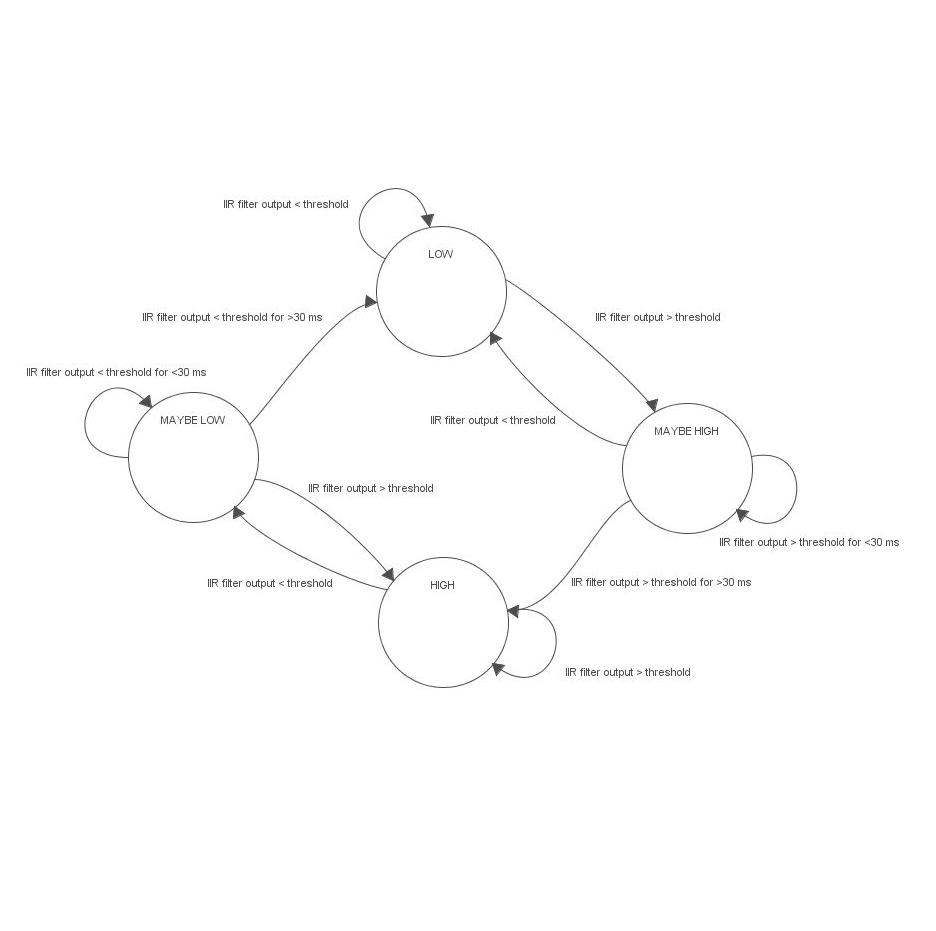
Figure 3: IIR FSM
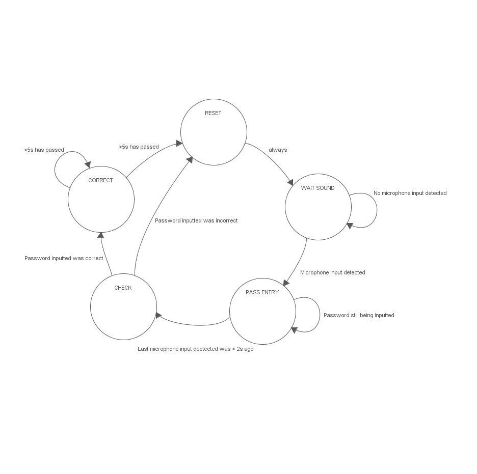
Figure 4: Verification FSM
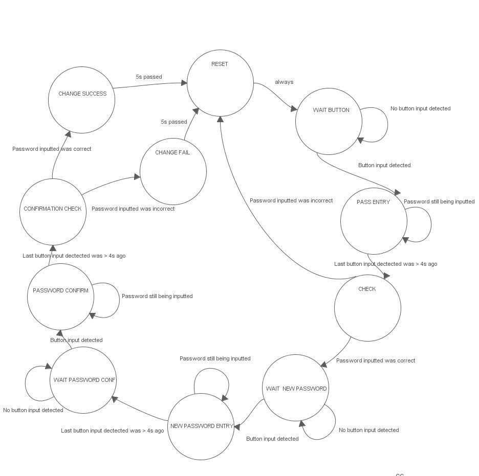
Figure 5: Button/Password Set FSM
Three state machines were used in this program: one for the IIR filter to determine whether the microphone input is actually 420 Hz, one for the buzzer input Morse code decode, and one for the button input Morse code decode. The state diagrams are shown.
While the IIR filter does a good job of filtering frequencies that are not 420 Hz out, there are still times when the output from the filter go above or below the threshold when it shouldn’t. The IIR filter state machine ensures that false positives and negatives are not placed into the input buffer. Only when the output is consistently above or below the threshold is the state set to HIGH or LOW and the times noted.
There are 5 states in the microphone input morsecode FSM: RESET, WAIT SOUND, PASS ENTRY, CHECK, and CORRECT. In RESET, the data arrays related to the microphone input is cleared so that new input and characters can be accepted. In WAIT SOUND, the microphone waits for user input. When user input from the apartment buzzer arrives and the state of the button input is WAIT BUTTON, the state of the microphone input goes to PASS ENTRY, where the password is being inputted and decoded. The TFT also shows what the current input is being interpreted as. When microphone input stops, the FSM goes to a CHECK state. If the password is correct, the solenoid is turned on in the CORRECT state. Otherwise the state machine goes back to the RESET state.
The FSM for the button input is similar to the FSM for the microphone input except now there are more opportunities to enter a password and the input is through a physical button. As in the other FSM, this FSM will stay in the WAIT BUTTON state unless user input is detected and the state of the microphone input FSM is WAIT SOUND. After the first password input is entered in correctly, the FSM goes from CHECK to WAIT NEW PASSWORD, where the FSM waits for a new password to be inputted by the user. After the new password is entered in NEW PASSWORD ENTRY, the user has to confirm the password by reentering it. Only when the new password is confirmed is the password actually changed. After that, the FSM goes back to the RESET state.
Decode Morse Code
A big design challenge was decoding the inputs into actual Morse code. The IIR filter FSM captures the time between the transitions from LOW to HIGH and vice versa, in effect giving us the period that the buzzer is held down for and not pressed at all. The input capture for the button does much of the same thing. However, knowing these capture periods is just the first step. The microcontroller needed to distinguish between dots and dashes, the fundamental building blocks of Morse code. The device should operate with multiple users with multiple timing methods, so the timing of the dots and dashes should be dynamic. A dash should also be around the time of 3 dots, and there should be a pause of a dot length between inputs within a character and a pause of a dash length between characters. As user input timing is likely to heavily fluctuate, the timing of a dash was defined to be anything more than two the length of a dot. The length of a dot was defined by averaging out all the smaller input capture periods.
Each capture period is placed into an input buffer first. From there, the PIC32 determines whether each capture is a dot or dash. After that, a tree traversal of the Morse tree shown in the High Level Design page is done, and the correct character found and placed into a character array. As this process occurs in real-time and while the user may still be inputting characters, the characters shown on the TFT screen may change from what the PIC initially thought the characters were.
The IIR Filter
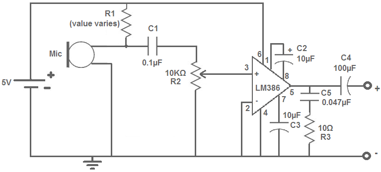
In order to allow the system to be able to operate in a noisy environment and only be triggered by the buzzer, a narrow bandpass filter was used. The buzzer sound was recorded from one of the local apartments - the baseline for the design. By observing the FFT of the buzzing sound, there was a 210 Hz fundamental frequency with a strong harmonic at 420 Hz. Because the 420 Hz peak was stronger than the 210 Hz peak and more out of the noise floor, 420Hz is used as the testing frequency for buzzer sounds. Since every apartment buzzer is going to be slightly different the filter will need to be modified to match the system. For this reason the filter was implemented in software instead of an analog filter. By using a software filter, only a few coefficients need to be changed to adjust to a different buzzer system. Indeed, it would be possible to implement an additional feature which automatically generates these coefficients for a new buzzer sound.
The first digital filter attempted was a Finite Impulse Response (FIR) filter. This was chosen due to the simplicity in implementing this type of filter. However, the filter would need at least 20 taps to get a reasonably small passband. This corresponds to 20 multiplies per sample. With the sample rate of 7812.5 Hz, this is possible to do on the PIC32. However, an Infinite Impulse Response (IIR) filter instead would allow a smaller pass band while only using 4 taps, which requires 8 multiplies. Since the performance was improved, while the number of calculations was over halved, the IIR filter is used. The coefficients for both the FIR and IIR filters were calculated using Matlab’s filter builder. The filter was set up to have a passband from 410 Hz to 430 Hz with a sample rate of 7812.5 Hz (figure 8).
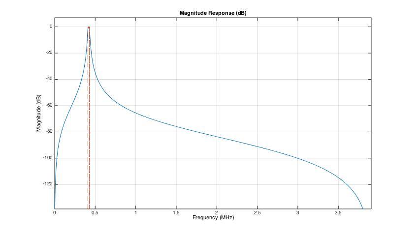
Figure 8: Frequency response of the IIR filter
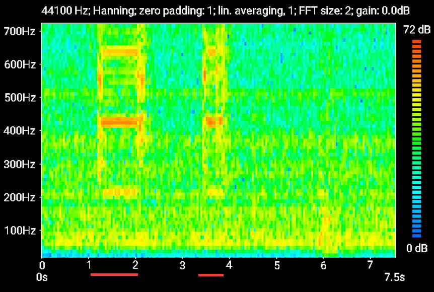
Figure 6: Spectrogram of the buzzer sound (Buzzer is active durring the period indicated by the orange-red lines)
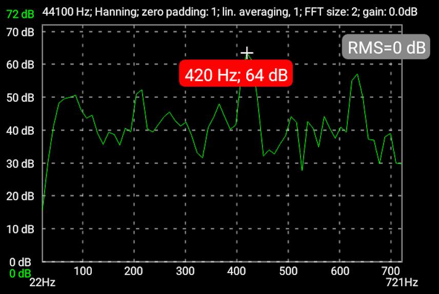
Figure 7: Frequency spectrum of the buzzer sound. 210 Hz fundamental with a strong harmonic at 420Hz.