"PID" Controller Performance
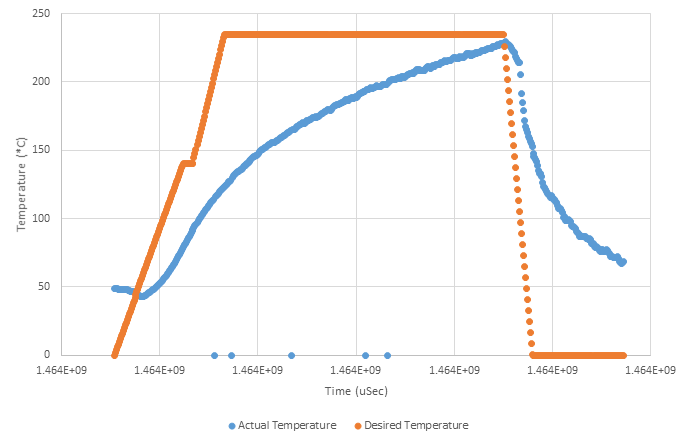
The PID controller implemented allowed for the temperature of the devices to be maintained to a certain degree. Due to the slow heat up time of the heating elements, it took longer than desired for the oven to reach temperature. This is seen especially well in the graph provided. As seen, the orange dots represent desired temperatures in time while the blue dots represented actual temperatures in time. The desired tempearture escalates rather quickly. Originally, the temperature is above the desired point. The heating coils quickly have to turn on to catch up to the desired temperature. This results in a delay at the peak reflow temperature while the oven waits for the temperature to rise. In this instance, there is not a direct influence from the PID controller affecting the graph. The two times it handles changes the output are prior to the original heat up and after the peak. Disclaimer: the data taken from this graph was measured with the oven in a rather cold room, this may have affected results.
Door Automation Performance and Redesign
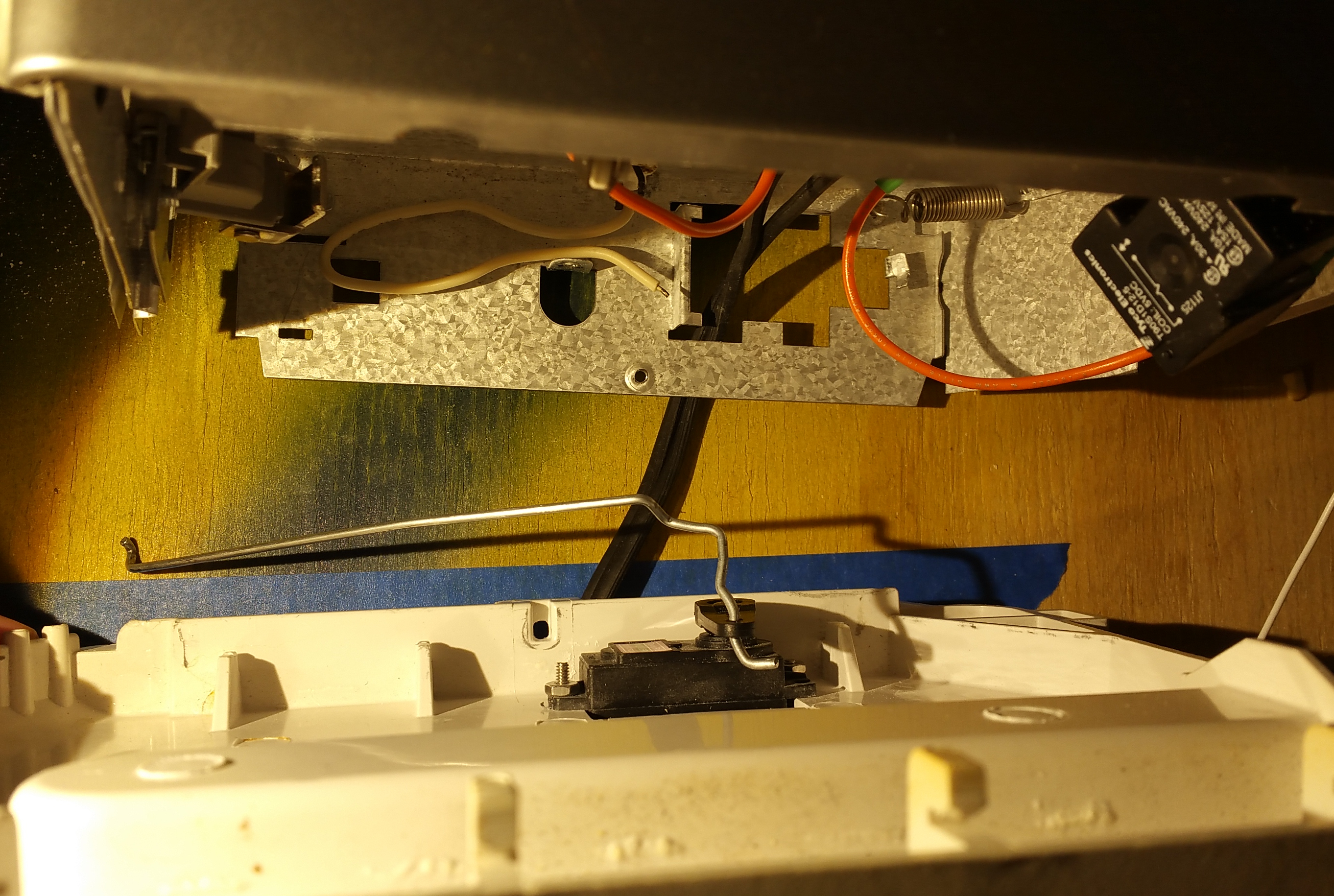
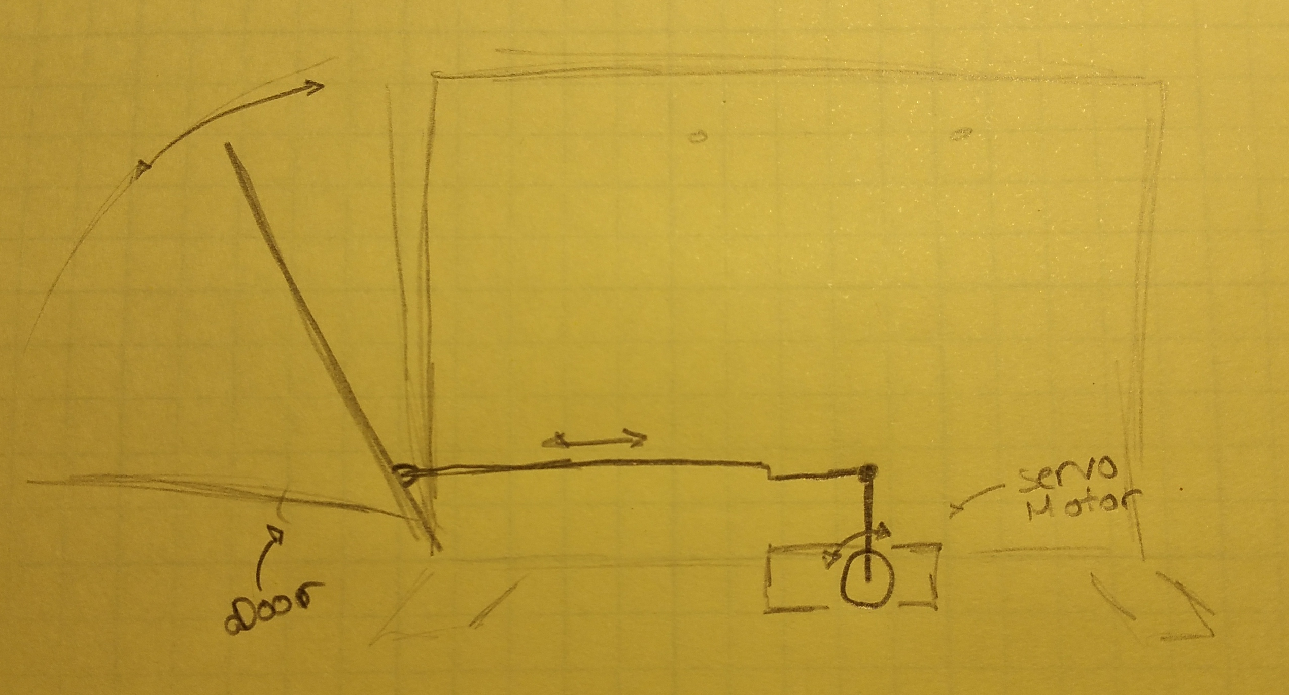
The designed implementation of the door results in a very violent shake of the oven as a whole. When the temperature reaches the desired temperature or more, the door slams open. This results in either of two things: the solder pasted components become unseated and are out of position; or the board itself becomes unseated from its platform. Both result in a failed reflow. When the temperature dips back down closer to the desired temperature, the door slams shut. A similiar result occurs. In its current state, attempting to control the door more fluidly by slowly increasing the servo's duty cycle and thus its degrees, fails. In application, there is a point in the duty cycles where the door is either all the way shut or all the way closed, nothing in between. This means no fluid opening or closing of the door. To combat this issue, two solutions come to mind: Either remove automation of the door all together or just automate the opening of the door at the end of the cycle. This of course removes any quick passive cooldown that the PID controller could utilize. The below pictures are drawings and implementations of the original design.
Door Mechanism from Above
Sketch of Door Mechanism from Side
TQFP and 0805 Packages
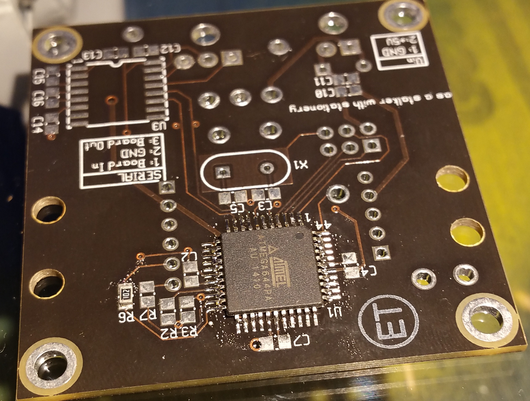
The TQFP and 0805 surface mount packages were the primary testing components. The solder paste used is Sn63 Pb37. In both cases, due to the door slamming shut and jolting the whole mechanism, the placement of the components moved and was altered just a bit. This did not affect the performance of the reflow oven in reflowing the solder on the pads and pins of each device. The reason for testing these two packages is due to there high probability of usage with this reflow oven. The oven is expected to be utilized by members of the Cornell University Autonomous Underwater Vehicle Project Team.
The Test Board with TQFP and 0805 Packages Reflowed on
Other Performance Issues and Concerns
The oven itself is inherently hot. For about 15 minutes or so after heating up, the oven has to cool down before any temperature is reached where it is safe to touch and pick up/move. Increased insulation within the heating system may assist in this. Included in the heating problem, is the issue where if not watched properly, the wires soldered to the heating elements can get desoldered due to the high temperatures and low solder melting point. This can be remedied by either using a higher melting point solder or by mechanically fixing the wire to the heating elements. Also, there were issues with setting up hardware SPI as the device, even when enabled, would not show up in the "/dev" directory of the raspberry pi